
HVR250 (250V) Series

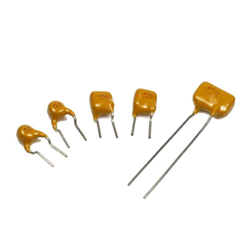
HVR250 (250V) Series
Type:HVR250
.Radial Leaded Devices
.Cured, flame retardant epoxy polymer insulating material meets UL 94V-0 requirements
.The High Voltage Radial devices (HVR Series), a Polymer-based Positive Temperature Coefficient (PPTC) device is suitable to protect telephony equipment against lightning and power cross strike, that is fully compatible with telecommunication standards.
.The High Voltage Radial devices are designed to provide different hold current product series offering 250Vac (Vmax interrupting) and 60Vdc (Vmax operating) and with low resistance.
.Cured, flame retardant epoxy polymer insulating material meets UL 94V-0 requirements
.The High Voltage Radial devices (HVR Series), a Polymer-based Positive Temperature Coefficient (PPTC) device is suitable to protect telephony equipment against lightning and power cross strike, that is fully compatible with telecommunication standards.
.The High Voltage Radial devices are designed to provide different hold current product series offering 250Vac (Vmax interrupting) and 60Vdc (Vmax operating) and with low resistance.
Introduction
PPTC HVR250 High Voltage 250V DC Series
- Radial Leaded Devices
- Cured, flame retardant epoxy polymer insulating material meets UL 94V-0 requirements
- The High Voltage Radial devices (HVR Series), a Polymer-based Positive Temperature Coefficient (PPTC) device is suitable to protect telephony equipment against lightning and power cross strike, that is fully compatible with telecommunication standards.
- The High Voltage Radial devices are designed to provide different hold current product series offering 250Vac (Vmax interrupting) and 60Vdc (Vmax operating) and with low resistance.
Product Conformity
- UL, CSA, TUV
- EU RoHS, REACH
Electronic Characteristics
| MODEL | V max. VDC Vint/Vop | I max. Amps. | Current (A) | R min. (Ohms) | R$_{1}$ max (Ohms) | Time To Trip | Pd typ. (W) | ||
|---|---|---|---|---|---|---|---|---|---|
| I hold | I trip | Current (A) | Time (sec.) | ||||||
| HVR250P080CF | 250/60 | 3 | 0.08 | 0.16 | 15 | 33 | 0.35 | 4.00 | 1 |
| HVR250P080CFT | 250/60 | 3 | 0.08 | 0.16 | 15 | 33 | 0.35 | 4.00 | 1 |
| HVR250P120CF | 250/60 | 3 | 0.12 | 0.24 | 4.00 | 16.00 | 1.00 | 2.50 | 1 |
| HVR250P120CF-RA | 250/60 | 3 | 0.12 | 0.24 | 7.00 | 16.00 | 1.00 | 2.50 | 1 |
| HVR250P120CF-RC | 250/60 | 3 | 0.12 | 0.24 | 5.40 | 14.00 | 1.00 | 3.00 | 1 |
| HVR250P120CF-RF | 250/60 | 3 | 0.12 | 0.24 | 6.00 | 16.00 | 1.00 | 2.50 | 1 |
| HVR250P120CF-R1 | 250/60 | 3 | 0.12 | 0.24 | 6.00 | 16.00 | 1.00 | 2.50 | 1 |
| HVR250P120CF-R2 | 250/60 | 3 | 0.12 | 0.24 | 8.00 | 16.00 | 1.00 | 2.50 | 1 |
| HVR250P120CF-R3 | 250/60 | 3 | 0.12 | 0.24 | 8.00 | 16.00 | 1.00 | 2.50 | 1 |
| HVR250P120CFT | 250/60 | 3 | 0.12 | 0.24 | 7.00 | 16.00 | 1.00 | 2.50 | 1 |
| HVR250P145CF | 250/60 | 3 | 0.145 | 0.29 | 3.00 | 14.00 | 1.00 | 2.50 | 1 |
| HVR250P145CF-RA | 250/60 | 3 | 0.145 | 0.29 | 3.00 | 12.00 | 1.00 | 2.50 | 1 |
| HVR250P145CF-RB | 250/60 | 3 | 0.145 | 0.29 | 4.50 | 14.00 | 1.00 | 2.50 | 1 |
| HVR250P145CFT | 250/60 | 3 | 0.145 | 0.29 | 5.40 | 14.00 | 1.00 | 2.50 | 1 |
| HVR250P180CF | 250/60 | 3 | 0.18 | 0.65 | 0.8 | 4.00 | 1.00 | 20.00 | 1.80 |
| HVR250P180CFT | 250/60 | 3 | 0.18 | 0.65 | 1.40 | 4.50 | 1.00 | 21.00 | 1.80 |
* V max. = Maximum voltage the device can withstand without damage at rated current.
* I max. = Maximum fault current the device can withstand without damage at rated voltage.
* I hold = Hold current - maximum current at which the device will not trip at 20°C still air.
* I trip = Trip current - minimum current at which the device will always trip at 20°C still air.
* R min. = Minimum device resistance at 20°C prior to tripping.
* R 1max. = Maximum device resistance at 20°C measured 1 hour post trip.
Product Packaging
- **Standard Package:** 500 PCS per polybag.
Product Inquiry
| Image | Product Name |
|---|---|
|
HVR250 (250V) Series HVR250 |